The 36 ft boom
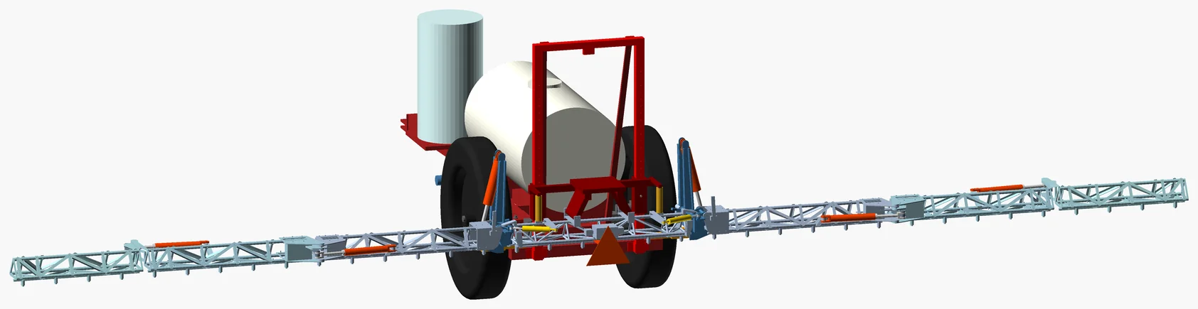
A 36 ft aluminium spray boom on its own 300-gallon trailer sprayer. Folded, the whole machine goes through a 10 × 10 ft door. A checked 3D model; nothing built yet.
What it has to do
Thirty-six feet is nine strawberry rows on 4 ft centres. A nozzle every 12 in puts two over each row, 6 in either side of the row’s centre, and two over each aisle: 36 nozzles.
Folded, the whole sprayer has to go through a 10 × 10 ft door: no taller than 10 ft, and about 9 ft wide at most, so it is comfortable on the road and in the doorway. At the low stop it is 8 ft 3 in tall and 7 ft 5 in wide. Lifted, it would be about 12 ft, so it travels at the low stop.
How it folds
Each side has three sections: a wing, a middle and a tip, and every fold is hydraulic. The wing folds up on a hydraulic cylinder that rides on the breakaway yoke. Every cylinder is a common farm-store ASAE size. The middle and the tip each swing 180° flat on a 2 × 8 through a bell crank and link, the linkage a Ferguson patent and AGCO’s pull-type booms use for a 180° fold. Open, each 2 × 8 is fully extended, so the cylinder itself is the stop. Folded, a 3/4 in stroke-control segment clipped on its rod — the stop farmers put on tillage cylinders to set depth — makes it bottom out at exactly 180°, so it is the stop that way too, and the force stays inside the cylinder. The wing cylinders are the 3 × 8 size, with the same length and pins, because they lift more. Folded, the three sections stack front to back behind the trailer and ride up with the wing.
The wing cylinder bottoms out exactly when the wing is folded, so the cylinder itself is the transport stop, and it cannot be driven over centre. A second fold per side follows Hardi’s PRO booms, which fold 39 ft and 49 ft booms into one transport width. Folding the wings flat along the trailer was ruled out, because a 45 ft front fold on a small trailer is 10 ft wide.
A breakaway on each side
This boom runs close to deer fences, so each whole side — wing, middle and tip together — can swing back or forward if it hits a post or the tractor stops hard. It hangs on a hinge tilted 15°, so the side rises as it swings either way, and gravity brings it back down to straight. Toro and AGCO tilt their breakaway hinges the same way. Gravity alone is too weak to hold a 5 m side still over bumps, so a spring-loaded roller sits in a notch and lets go at about 25–45 lb pushed near the end. Once it lets go, gravity returns the side and the roller drops back in. A truck shock damps the return, and urethane stops on the shock end the swing.
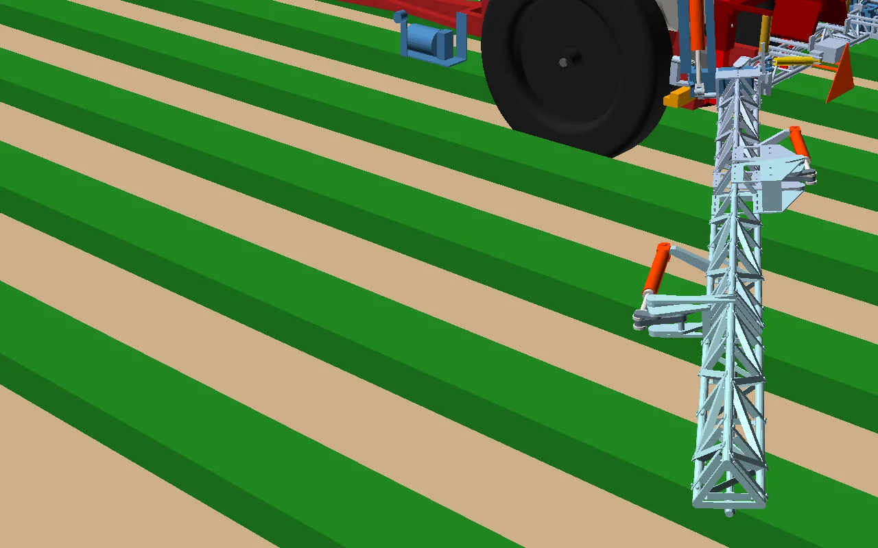
On the road the sides can’t swing: as each wing folds, a tongue on its root drops into a catch on the centre section. Nothing is pinned by hand.
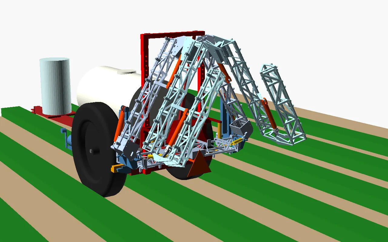
The joints, unfolding
What it is made of
A three-tube triangular truss, like a radio tower: 1-1/4 in 6061-T6 chords, braced with aluminium angle bolted through the tubes, the way bolted lattice towers are braced. Nothing aluminium is welded, because welding roughly halves 6061-T6’s strength next to the weld, and a cracked weld is how aluminium booms fail. Every hinge is welded steel, plugged into the tube ends and bolted, and the centre section is welded steel. The pins are steel in replaceable bushes. The truss is 6 in deep, about the deepest that still folds 18 nozzles a side into the old boom’s space.
Getting it ready to build
Before drawing joints to build from, the whole open boom was checked as a truss at 3 g of bounce. No standard sets a load for spray booms. Field measurements put a rigidly mounted boom tip near 3.6 g, and the breakaway, the float and the stops take the spikes beyond that. Four things changed:
- The folds lock open on the cylinders’ own stops. In round 3, a 45 lb push at the tip would have put about 1,900 psi in the middle fold cylinder. The re-solved linkage holds the same push at about 335 psi, and three of the four directions now rest on a cylinder’s end stop with no oil in the path.
- The centre is welded steel. It carries both sides’ bounce, and bolted aluminium there would have worn out in fatigue in about nine years of spraying.
- Every hinge is steel. The middle fold’s pin sits 300 mm behind the truss, so the folded sections can nest. That makes the joint’s bending arrive at the pins as about 13 kN pulling and pushing, 300 mm off the tubes. So the last 200–250 mm of each section there is a steel end block, with a top plate on the top tube, a bottom plate across both bottom tubes, and a closed box behind. All of it is through-bolted to the aluminium, and nothing aluminium is welded. The wing’s root is a steel block too, carrying the wing pin and its rest pad.
- Bigger wing cylinders. All of this weighs more, so the wing cylinders went up to 3 × 8. That is the same length and pins as before, at about 2,340 N·m against the 1,620 needed to lift an open wing.
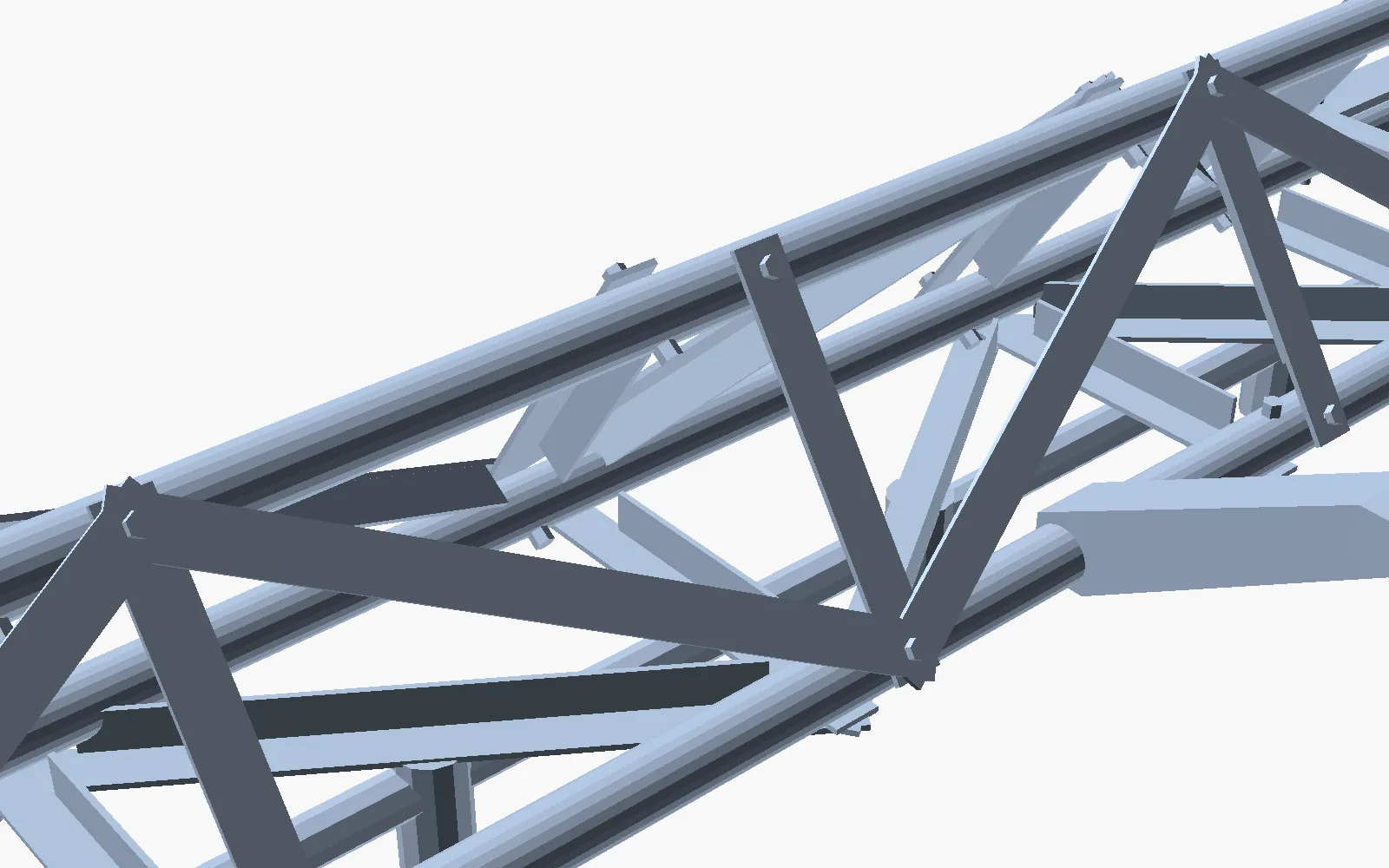
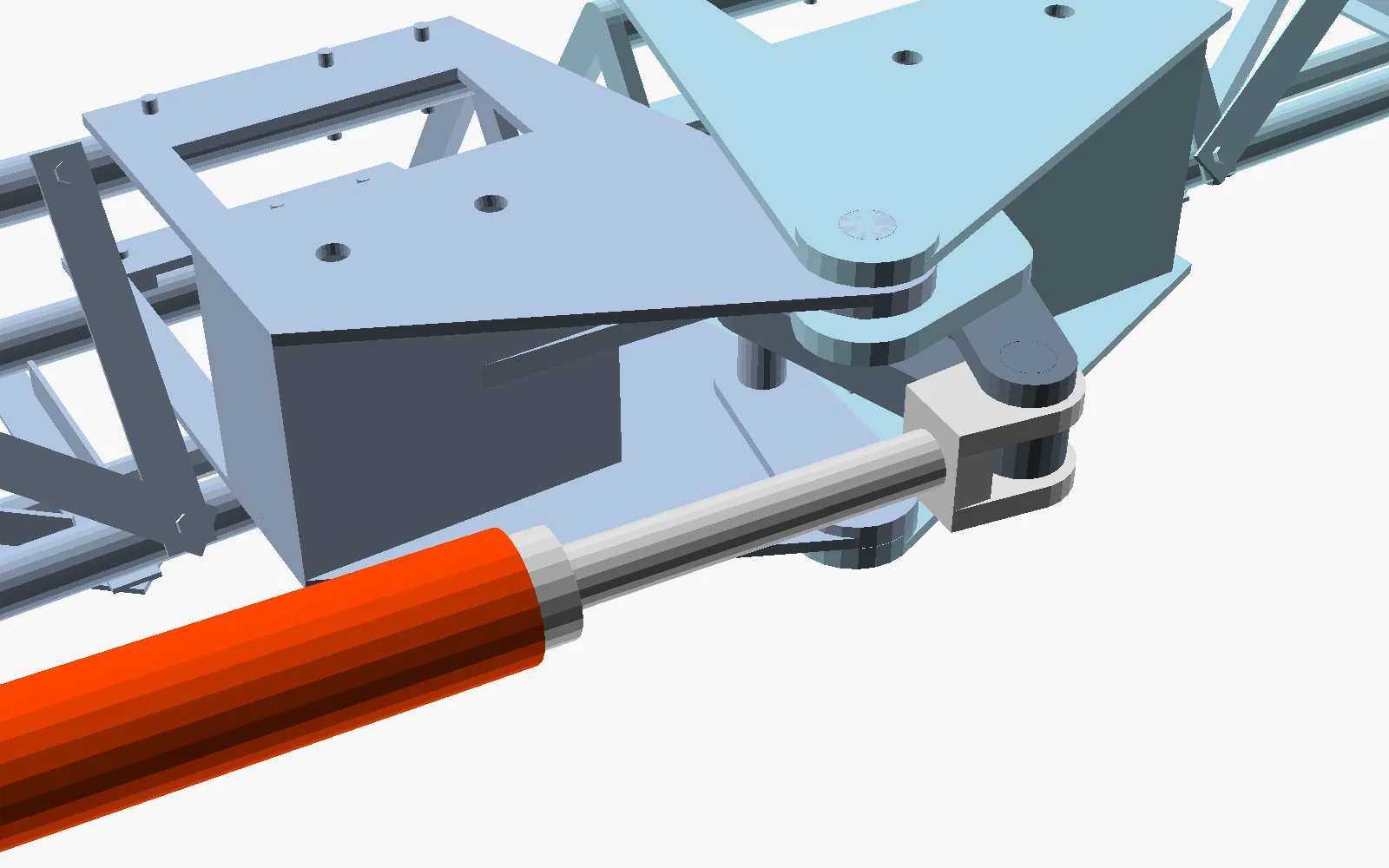
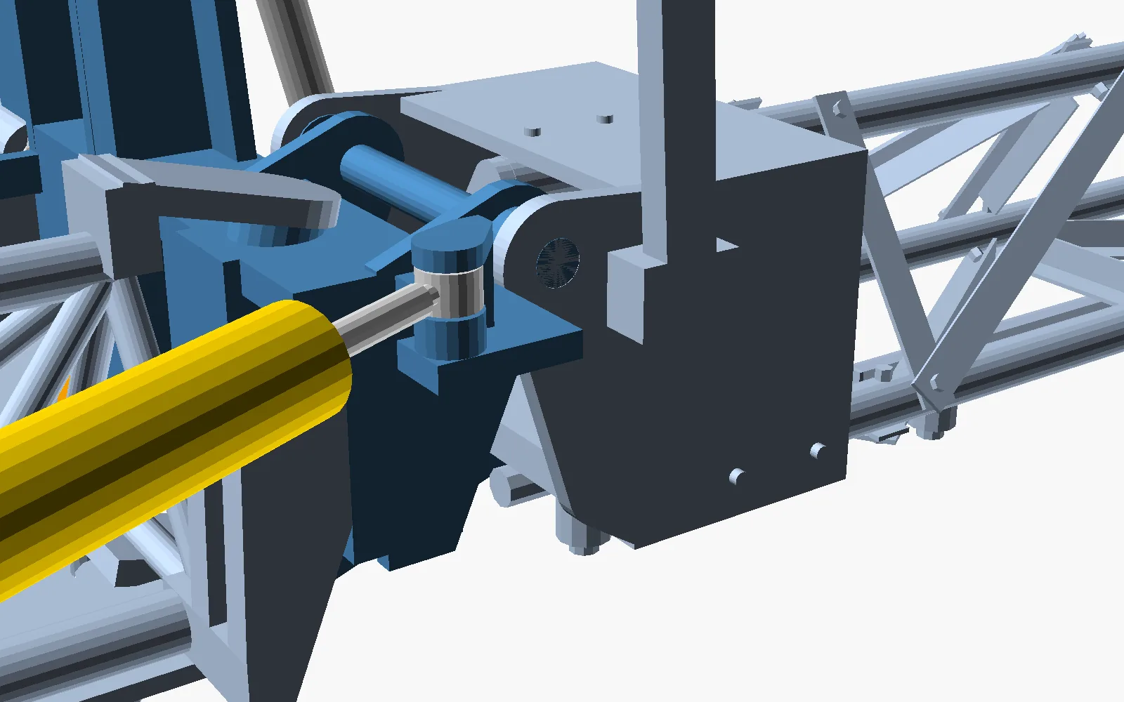
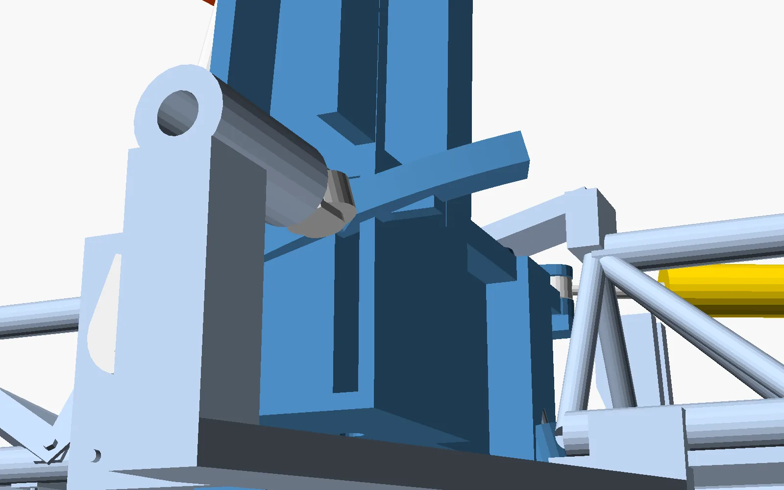
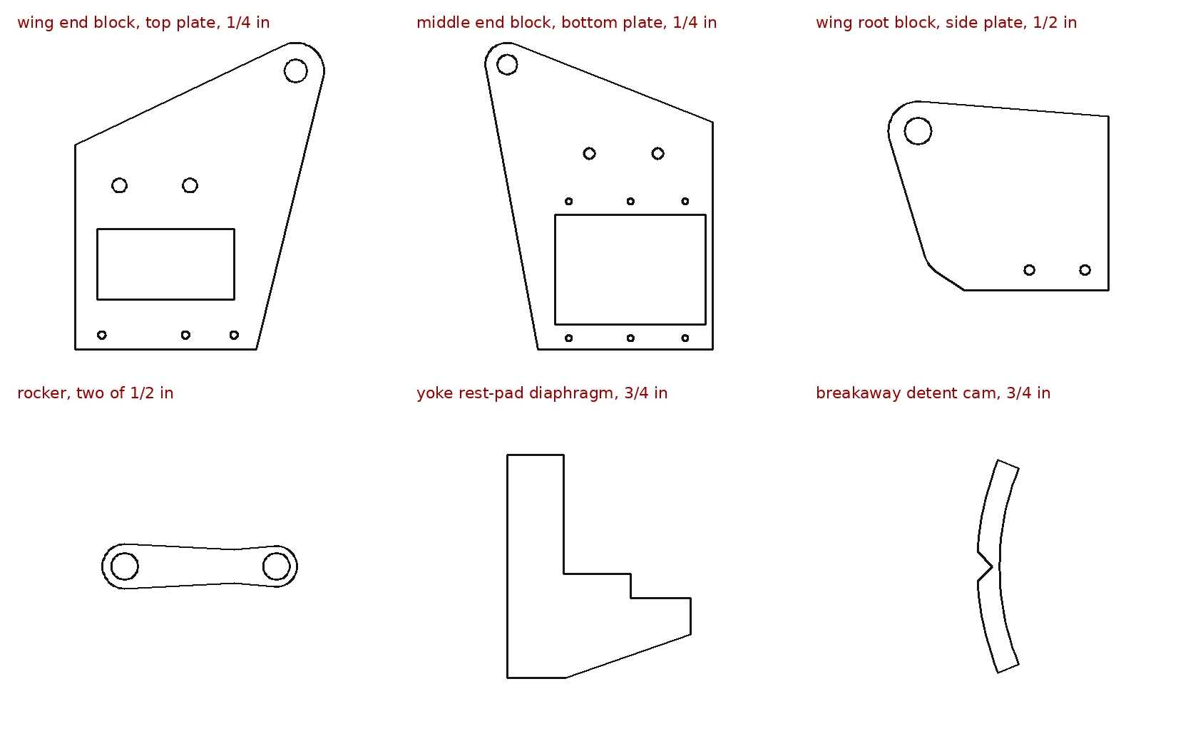
The cut list comes straight from the model: 198 angle braces (178 ft of angle) and 18 chord tubes in aluminium. Every steel plate, 50 kinds, is drawn as a cut file that a laser-cutting service or a CNC plasma table can use directly. Pin holes are drilled through each pair of lugs together after welding, so the pins line up. The cylinders are the farm-store kind, with clevises welded on both ends, so every joint they drive is a 1 in tang that fits the clevis.
The welds
Every weld on the boom is steel to steel; the aluminium is all bolted. The schedule lists 46 joints over seven weldments: each one’s fillet size, length, the load it carries and what it can take. That comes to 52 m of weld and about 8 kg of MIG wire for the whole boom. The fillets are sized for 3 g of bounce, or for a cylinder held against its stop at the tractor’s full pressure, whichever is worse. The hardest-worked, the seams of the yoke’s box, run at 80 % of their allowable.
Sizing the welds showed three steel parts that would have bent, so they changed before the welds were finished. The arm the wing rests on became a deep plate running up through the yoke. The mast the wing cylinder pulls on got flanged edges and stands on a closed steel box under the yoke. And the plate holding the top of the rocker’s pin runs right through its end block. The steel bars inside the aluminium tube ends are bolted, not welded, because that steel (4140) cracks unless it is preheated.
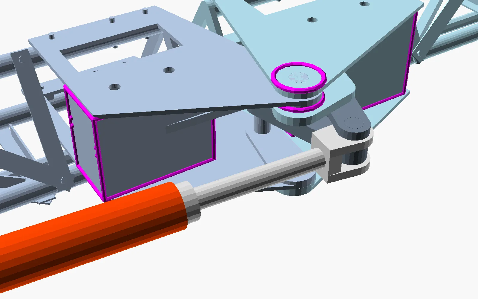
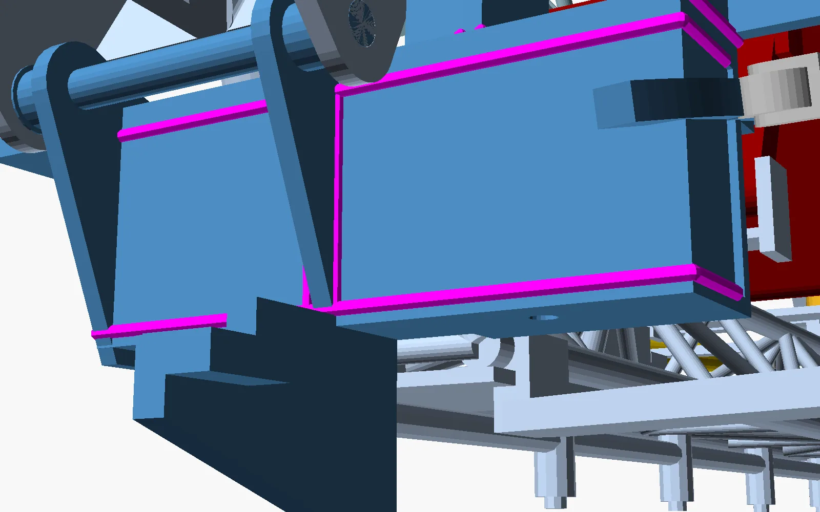
Before the rest is built, one wing is built and tested on its own for bounce and release force.
Raising and lowering
The boom hangs from a carriage that slides up two towers bolted to the back of the trailer on plastic wear pads. A hand-cranked brake winch moves it, the kind with an automatic brake that grain augers use. A boat-trailer ratchet winch is meant for pulling along the ground, not for lifting. A pin through the towers carries the boom; the winch only moves it. That gives 45 in of travel: the nozzle tips go from 28 in off the ground over strawberries to 73 in over low sweet corn.
Pins and bushes
Every pin turns in the same bush: a steel shell lined with PTFE, 1 in bore and 1-1/8 in outside, the kind Hardi sells for its own booms. It runs dry, so there is no grease nipple to miss, and it is pressed into whichever part turns. The pins are 1 in hard-chrome rod, the stock cylinder rods are made from. Each is held still in the other part by a keeper plate in a slot across its end. That makes 50 bushes on the boom. Where a section’s weight sits on a joint, it rests on a PTFE-lined thrust washer; there are 10. The bushes are sized for the worst load each joint can see. The hardest-worked are in the fold linkage’s coupler, at three quarters of the bush’s wear limit.
Levelling
The centre section hangs from the carriage on a trapeze: two wide links on 1 in pins, closer together at the top, with two spring-and-shock units. The wide pins take the twisting load of a turn or a breakaway hit as well as the roll, like Demco’s floating mount. While spraying, each wing rests on a rubber stop with its cylinder in float, so bumps go into the springs and not into trapped oil. A wing’s cylinder can lift it off the stop to clear something. A ground-height controller can be added later; it would need its own oil supply, because the tractor’s hydraulics are already busy driving the spray pump.
Hydraulics
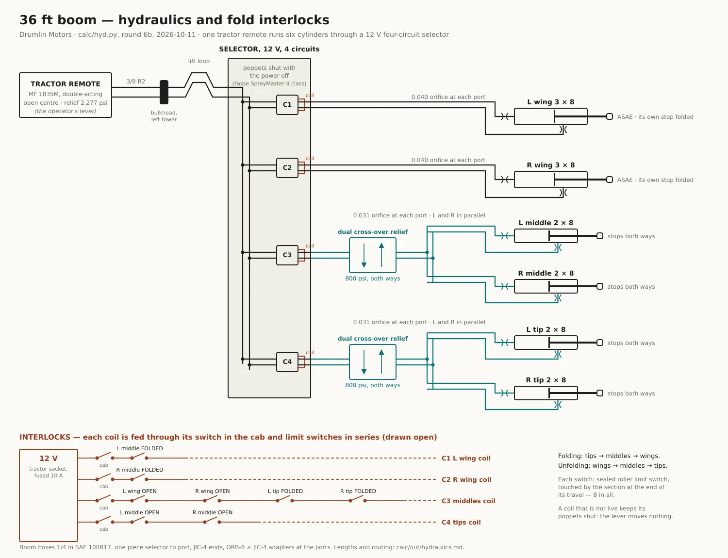
One free tractor remote runs everything through a 12 V four-circuit selector, the kind sold for sprayer booms: left wing, right wing, both middles, both tips. Its valves stay shut with the power off, so a bumped lever moves nothing. Eight sealed limit switches keep the order, as Hardi’s stop switches do. The middles won’t fold until the tips are in, and the wings won’t fold until the middles are in. Unfolding runs the other way.
A small orifice at every cylinder port, as Demco fits, keeps each fold slow. A 2 × 8 on the tractor’s full flow would snap shut in under half a second. With the orifices, the middles and tips take 14 to 17 s each way, and a wing takes about 22 s up and 12 s down. The tractor’s relief is 2,277 psi. The middles and tips only swing level and need about 335 psi, so a relief on each of those circuits holds them to 800 psi. If a fold were blocked near open at full pressure, its linkage would overload the coupler’s bush. The wings lift their own weight, so they keep the tractor’s full pressure.
The boom carries 12 hoses, each one piece of 1/4 in hose from the selector to its port. Every loop across a joint is sized to the farthest its two clamps ever get apart, checked at 401 positions through the breakaway, the lift and every fold. At the middle fold the folding plates sweep a circle about 870 mm across, so the tips’ hoses cross above the joint on a swivel clamp on top of the pin.
The trailer
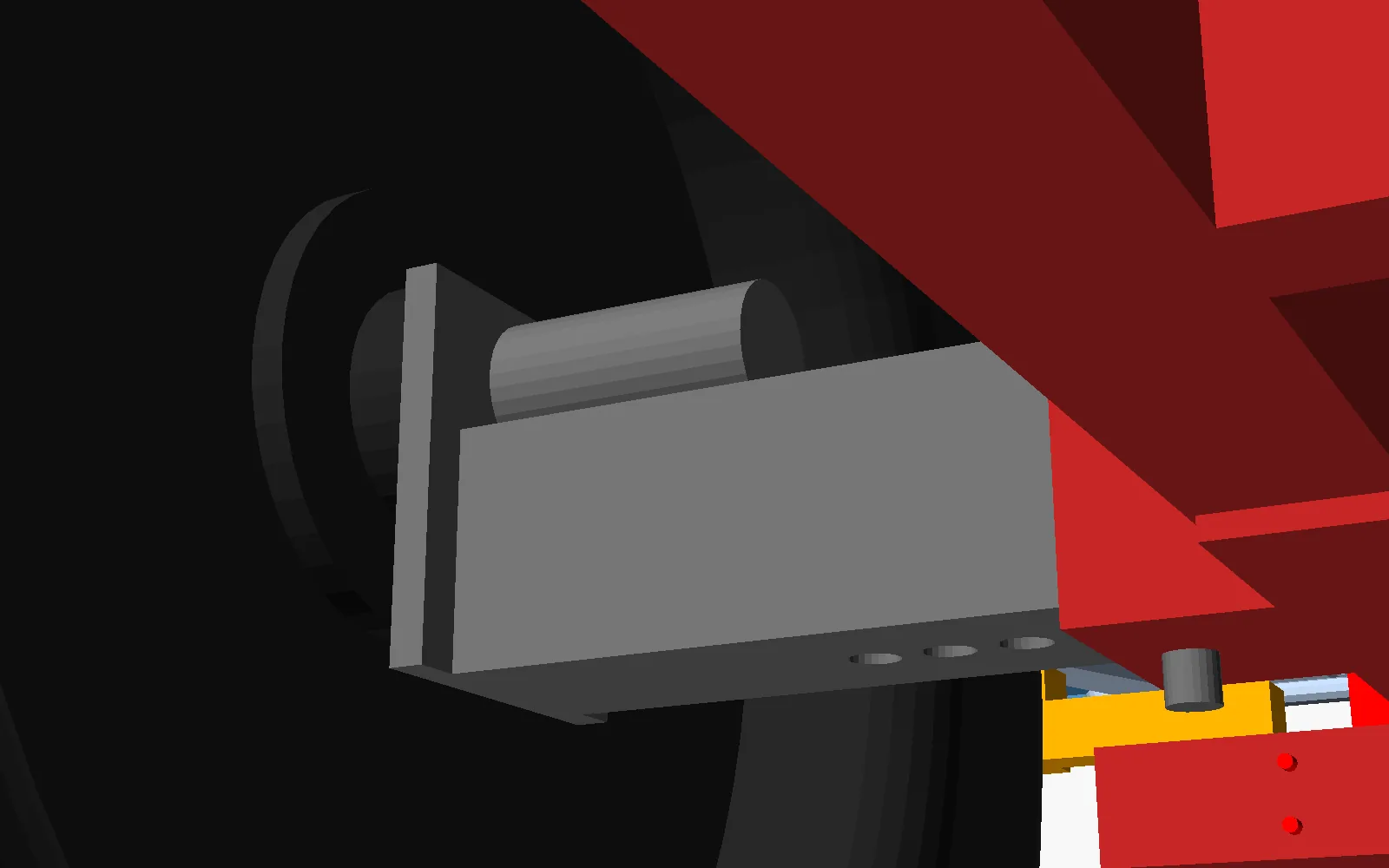
The boom rides on a trailer designed for it. Jacob asked for big farm wheels and a track no wider than his MF 1835M on industrial tyres, 78 in. Each wheel is on a 5 in square stub that slides in the axle beam and pins at 54, 57, 60, 63 or 66 in centres, 65 to 77 in overall on 11.2-38 tyres, so the trailer straddles one strawberry row with its wheels in the aisles. Each hub is a 7,500 lb eight-bolt implement hub, its 3 in spindle welded along the top of the stub and through a 3/4 in plate across its end.
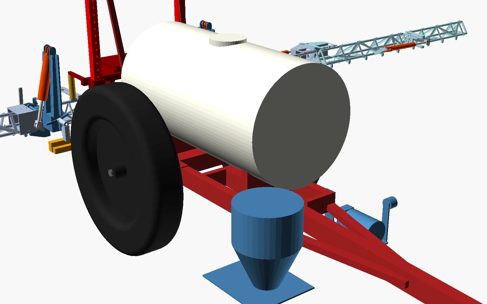
The 300-gallon tank is a round sprayer tank, 38 in across and 72 in long, just ahead of the axle in two welded cradles. Its sump is at the bottom centre, where the pump draws from. A 65-gallon clean-water tank sits up the tongue, for rinsing and to keep weight on the hitch: with the main tank empty and the boom folded, that tank must be full on the road, or the boom lifts the drawbar. Full, the trailer weighs about 6,100 lb, about 600 lb of it on the drawbar. It has no brakes, by Jacob’s choice.
The pump is the kind the farm already runs: a Hypro 9303 centrifugal on a hydraulic motor, on one tractor remote. It makes about 91 gallons a minute at 79 psi from the tractor’s 12.6 gallons a minute of oil, enough for 100 gallons an acre at 5 mph with a jet agitator running. The nurse trailer’s hose plugs into a 2 in camlock. The pump draws the water through it and pushes it through a Hypro Cleanload induction hopper into the tank, so chemical concentrate never passes through the pump. A 300-gallon fill takes about 5 minutes.
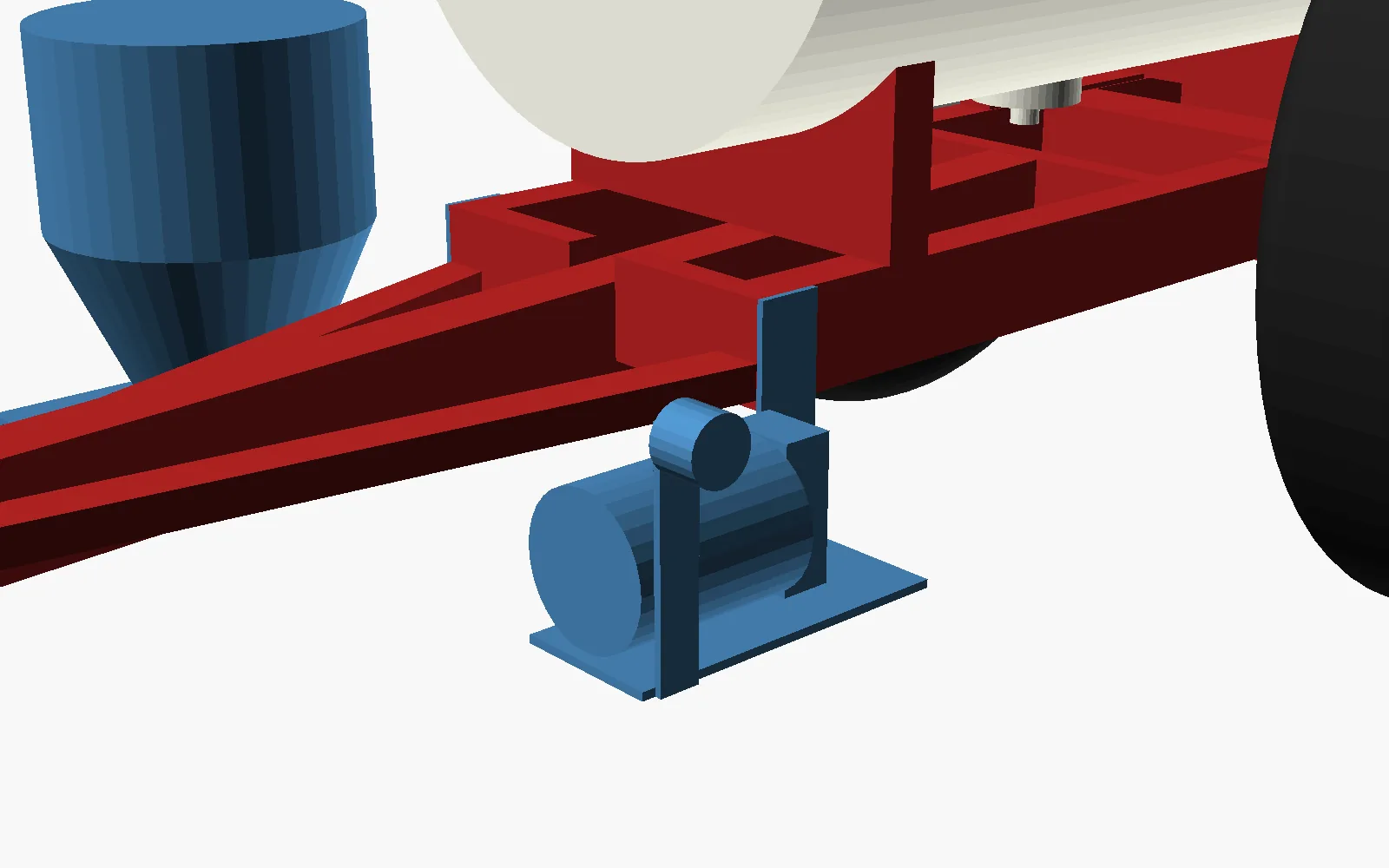
The frame is welded steel tube. It was checked at 3 g of bounce and against SAE J684’s hitch loads. A fatigue check, at the boom’s bounce for 100 hours a year, moved the rails up to 3 × 6 × 1/4 in tube and the axle beam to 6 × 6 × 5/16 in: the boom hangs behind the axle and works that joint on every bump. The tongue runs back between the rails to a crossmember under the tank, so no single weld carries the hitch. Lamps and the slow-moving-vehicle sign follow ANSI/ASAE S279: an amber flasher and a red tail lamp at each side, plugged into the tractor’s 7-pin socket.
In the field: a 2.5-acre strawberry block
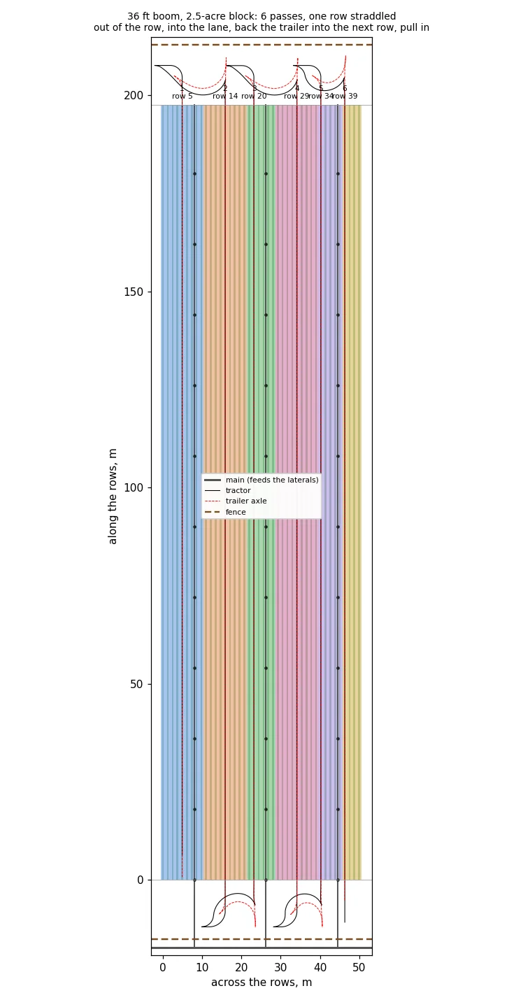
The trailer goes behind the farm’s MF 1835M, on a drawbar extended so the pin sits 0.8 m behind the rear axle instead of 0.4. Both straddle one row, with their wheels in the two aisles beside it; the trailer runs at its 54 in setting, which keeps its tyres well inside the aisles. The block is 42 rows on 4 ft centres and 650 ft long, with a deer fence across each end. Every 15 rows an irrigation lateral lies in an aisle, fed from a main outside the south fence. The laterals have 12 in risers, and the boom clears them by about 15 in.
Every nozzle is its own zone, with a 12 V shutoff on each nozzle body and a toggle switch for each in the cab: 36 switches, grouped by row. A nozzle sprays only over the field and only over a row not yet sprayed. That stops overspray past the field's edge and overlap on rows already done, and it is what spot spraying needs later.
At each end of a pass, every nozzle shuts off as it passes the row end. A 189 in tongue is too long to U-turn in a headland: the first simulation tried, and the tractor’s tyre would have met the tongue while the trailer’s wheels swung back across the row ends. So the tractor drives on until the trailer’s wheels are off the rows, stops, and folds one side of the boom. It pulls into the headland lane, away from the next row, then backs the trailer round onto the next row’s line, toward the fence. Then it pulls straight into the row and unfolds at the field edge, and each nozzle switches on again as it crosses into the field. Each turn takes under two minutes. The simulation checks every wheel at every step: in the field, each stays within 3 in of its line in an aisle. Moving the pin back lets the trailer swing to 83° before its front tank comes within 2 in of the tractor’s fender; the turns use up to 69°.
The headland has to be 50 ft, not 40. The backing turn needs about 47 ft from the row ends to the fence. A turn with no backing would need about 73 ft, and at the south end, boxed in by the laterals, none fits at any depth tried. The first turn also swings about 13 ft past the side of the block. The real headlands and the room beside the block have not been measured.
No wheel crosses a lateral, in the field or in the south headland where they feed in. That decides the order of the passes: every turn at the south end stays between two laterals, and the passes are picked so that every turn can be driven. The block takes six passes and about 22 minutes, 13 of them spraying. It uses 125 gallons at 50 gallons an acre or 250 at 100, one tank either way.
Status
Round 6b of the boom passes the shop’s solid checks: 46 parts, and no part touches another at any of 36 positions through a breakaway swing back and forward, the lift and every fold. Round 3 of the trailer passes the same checks with the boom on it: 57 parts, at the narrowest and the widest wheel settings. Folded, the whole sprayer goes through a 10 × 10 ft door. Two independent reviews shaped the boom’s rounds 2 and 3. The boom’s sizes were scaled from a photograph of the old one, and the towers’ and the hinge’s heights are assumed; there is no measuring trip, because the door is the only limit. The welds, the bushes and the hydraulics are scheduled; the selector and the reliefs are in the model. The hoses bend, so they are drawn for checking but not in the solid checks. A 6 in truss is shallow, so the first wing gets checked for bounce, and for its release force, before the rest is built.
Design basis: docs/BOOM36.md, models/boom36/ (round 6b, 2026-10-11), calc/boom36s.py, calc/bracket5.py, calc/welds.py, calc/bushes.py, calc/hyd.py, calc/boom36bom.py and the cut files in models/boom36/cut/. The trailer: docs/TRAILER.md, models/trailer36/ (round 3, 2026-10-12), calc/trailer.py, calc/trailerframe.py, calc/trailerknee.py, calc/trailerpump.py, calc/trailerplumb.py and calc/buytrailer.py. The field: calc/spray36.py and models/sprayer36/.